How To Create Effective Shop Drawings
Asking someone to make something for you is sharing many details with precision, and shop drawings are a universally understood system of doing so. This article will cover the basic principles you should know to help you make great use of on-campus facilities and off-campus businesses for typical student projects. A drawing that follows these tips can be understood by most people, although they are simplistic relative to the General Dimensioning & Tolerancing system that is used in the professional world, for professional needs.
Contents: |
Give us your 30-second thought about how we did today!
Pen & Paper and CAD
Hand-made shop drawings can be very efficient, especially if you are proficient in illustrating depth. But even if you can only draw roughly in 2D, hand-made drawings are useful notes for creating very simple parts and demonstrating to a shop manager what you want your part to do when you seek their input. If you never need to go beyond that, that's fine.
If you have a complex part or need to have many different parts made (or you want to pick-up a professional skill), spending a few hours to learn the basic use of a Computer-Aided Design program is worthwhile. These programs make producing and editing clean drawings very fast, and their drawings and models are simple to share with teammates and fabricators. The University of Rochester provides a number of CAD programs on school computers, see Fabrication Resources for more information.
Views and How to Arrange Them
A drawing is comprised of multiple illustrations of the part from different perspectives, called “views”. The sum of the information presented in all views should fully describe the features and their locations.
Presenting this information across multiple views will help your dimensions and tolerances be obvious, although spreading values over too many views makes finding something specific more difficult. Do what feels like an appropriate balance to you and get input from your facility's manager.
Axonometric Views
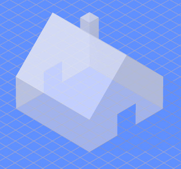
The Isometric/Dimetric/Trimetric views show most of a part's features at once and give the fabricator a clear picture of the whole part. It's a good idea to include one axonometric view on a drawing. Putting dimensions on this view is discouraged both because of to its complexity and because the perceived size of a feature is skewed by depth (an effect called "foreshortening").
Orthographic Projection
Most parts are best understood by illustrating them with perspectives that are 90° rotated from each-other, the Front/Left/Right/Top/Bottom views. It helps that the system is universally commonplace. Choosing which perspective of the part should be Front is a matter of what would make a clear drawing.
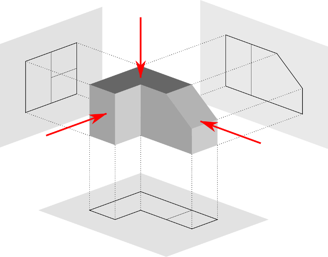
The most intuitive pattern of presenting the orthographic projection as a set of views is to show the Front view in the center, bordered by the other views as if you were rolling the part on a table. An axis of each view should line-up with the Front view's axes.
Sectional Views
Cross-Sectional View:
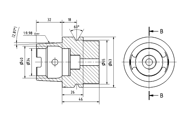
You can also combine orthographic and sectional views by simply replacing an orthographic view for a sectional view, or by placing the sectional view beside its corresponding orthographic view.
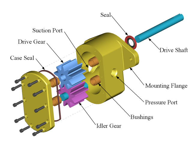
Assembly Drawings
If you are asking a fabricator to make multiple parts of a system, illustrating how these parts fit together will help them figure out an efficient fabrication process. The fabricator can also test that the parts are functional by making sure they fit together, and can perform difficult assembly processes for you. Assembly drawings typically use Disassembled and Sectional views.
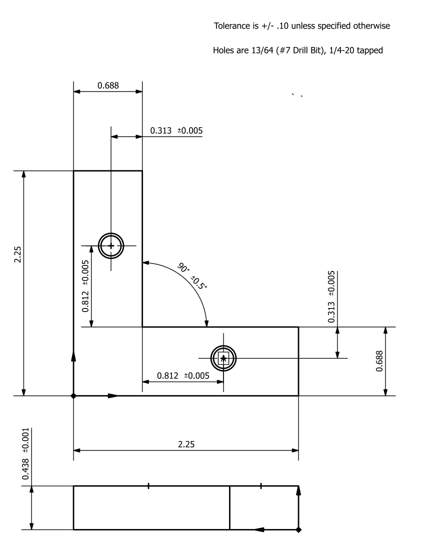
Indicating Dimensions Clearly
Clearly-presented information is understood correctly and quickly. Indicating feature sizes and locations using a few basic rules will go a long way to minimizing mistakes and use of the fabricator's time.
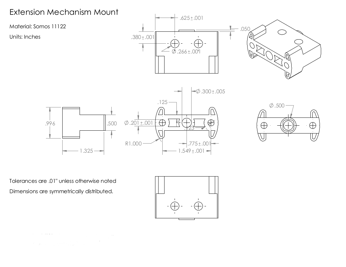
Indicate distances with double-headed arrows parallel to the length. You can decrease clutter by presenting dimensions away from the drawing view, using extension lines to clarify what feature is being referenced.
- Only indicate a dimension once on a drawing. Duplicate indications can be confusing, may be interpreted as referencing two different features.
- Try to put all the dimensions of a feature on a single view -- compromise to avoid clutter.
- Don't let dimension lines cross any other lines. It makes dimensions harder to interpret.
Angle indications follow a similar style.
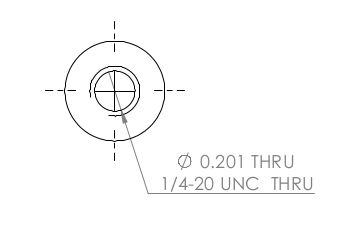
Holes should be indicated with a single-headed arrow next to the various specifications that describe the important features of a hole.
- Hole Diameter
- Hole Depth, or an indication that it passes through the entire body (THRU)
- Shape of the hole's bottom
- The type of thread in the hole if it's threaded
You can indicate the dimensions of a set of duplicate holes with a single indication by prepending it with the quantity of holes it applies to, i.e. "<Quantity of Holes> X <Specifications>". Note that this may actually be an unclear style if you have different holes with similar diameters in the drawing.
Applying Tolerances, aka Designing Around Reality
No fabrication process can get you exactly the dimension you want, only something within a range of values that we call the dimension's tolerance. There is error in every machine (which began as error in machine-making machines), and less accurate work is often faster work. A good drawing is incomplete without indicating what variability in each feature dimension acceptable to you, which depends on what you need the feature to do.
Fundamental Indications of Tolerances
Tolerance indications either sit next to the dimension or are listed elsewhere on the page if they apply to the drawing's dimensions in general -- setting a general tolerance means you only need to write the exceptional tolerances next to dimensions, which reduces clutter. There are three fundamental ways of communicating a tolerance:
- As a variation relative to an ideal dimension. 1.0" +/- 0.1" means .9" to 1.1" is acceptable. 2.54" +.05" means 2.54" to 2.59" is acceptable.
- As a range of acceptable dimensions, e.g. .9" to 1.1"
- As a maximum or minimum dimension, e.g. .9"MIN or 1.0"MAX
How you indicate tolerance is a matter of personal or organizational style as long as it's accurate to what you want. The important thing is that you are consistent so that your drawings are easy to follow.
Examples of Tolerance Indication
Length Tolerances
The maximum and minimum acceptable lengths of a feature depends completely on function, and there are too many possible functions to list here. Talk to a facility manager about what tolerances would work for your needs -- they'll also be able to tell you what tolerances are realistic with their equipment.
A few examples to give you a perspective on length tolerances:
- Most amateur fabricators can tell if something is +/- .5" within some specific length that is less than 1 foot long, and all shop processes can alter a part with more accuracy than that. Wider tolerances won't save fabrication time (again, assuming the scale is < 1 foot in length).
- +/- .01" can be attained by any student using a mill. Reliably making parts with +/- .005" precision is possible with some practice.
- Professional campus fabricators and students with a lot of machine shop experience are usually fine with +/-.001", and maybe +/-.0005".
- Machinists and high-precision facilities can achieve more precision yet. URnano has specialized equipment that can even reach micron and nanometer precision.
Hole Tolerances
Holes can be designed to fit shafts loosely or tightly, and getting the desired fit means keeping the hole diameter within a corresponding range of values.
Types of Shaft-Hole Fits and their Corresponding Tolerances
Through-Hole Sizes for Close and Loose Fits With Threaded Shafts
Tolerance Stack-Up
If the position of feature B depends on the position of feature A, the true tolerance in feature B's position is the SUM of feature A and B's positional tolerances. This is called tolerance stack-up, and it will quickly mess-up your part drawings if you don't take it into account. Even if you do account for it, stack-up forces your features to have tighter tolerances. The simplest way to deal with stack-up is to avoid it by making all dimensions dependent on the same features (using a datum is a simple and highly recommended method of doing so).